

Installation intructions (wiring)
Connecting the bridge to the alarm system is quite simple. Using four wires make the following connections:
- The CLK terminal on the bridge to the YEL terminal on the alarm panel.
- The DATA terminal on the bridge to the GRN terminal on the alarm panel.
- The + terminal on the bridge (P2(1)) to the AUX+ terminal on the alarm panel.
- The – terminal on the bridge (P2(2)) to the AUX- terminal on the alarm panel.
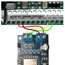
Probably, the terminals on the panel are already in use. Don´t disconnect the connected wires, just add the new ones from the bridge to the terminals.
Some panels can provide a maximum of 500 mA for all connected devices, including modules, powered detectors, relays, etc. If your installation shares the auxiliary output of your panel with other devices, make sure it can provide at least 300 mA for the BRDSC01.
The device requires 90 mA to operate properly, with a peak of 300 mA when starting up. If your panel cannot provide the necessary current, consider powering the BRDSC01 with an external source or from the battery.
Warning: Incorrect polarity connection can damage both the BRDSC01 and the alarm panel, voiding the warranty.
Because of the low voltage on the terminals, there is no risk of electric shock but while touching the wires, the alarm system could be triggered due the anti-vandalism mechanism. If this happen just disarm the system by entering the code on any keyboard.
If your alarm system is being monitored, be prepared to receive a contact from your monitoring service provider, in case alarm system is triggered. Other option is to put the monitoring service provider in aware of the installation beforehand, to make him dismiss the event.
What is the best location to place the device?
Alarm panels are typically installed in recessed cabinets within walls. Some cabinets are metal, while others are plastic. It will depend on the wall and the cabinet materials whether it is advisable to place them in the same cabinet as the alarm or outside of these, as metal cases or solid walls may interfere with the WiFi signal and disconnect the device from the network. If this happens (with concrete walls and/or metal cabinets), install the device outside the cabinet.
If your device does not have a plastic cse or you have removed it, be very careful not to place it on conductive surfaces that may cause short circuits.
The provided plastic case has perforations for screw mounting, but it is recommended to use double-sided tape to fixthe device.
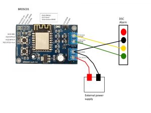
Powering the device from an external source
The recommended method to power the device is from the alarm panel itself. However, if opting to power the board externally or from tehe battery, it is imperative to ensure that the ground connections are aligned to prevent any potential damage to any of the devices. When utilizing an external power source, employ a DC12V and ensure both the external source and alarm system GNDs are connected together, as depicted in the following image.
Related:
– Registering your BRDSC01 Device and Getting Started
– Integrating BRDSC01 with Home Assistant
– Configuring BRDSC01 Devices
Back to Documentation index page