


Description
AWR12, your reliable IoT development solution
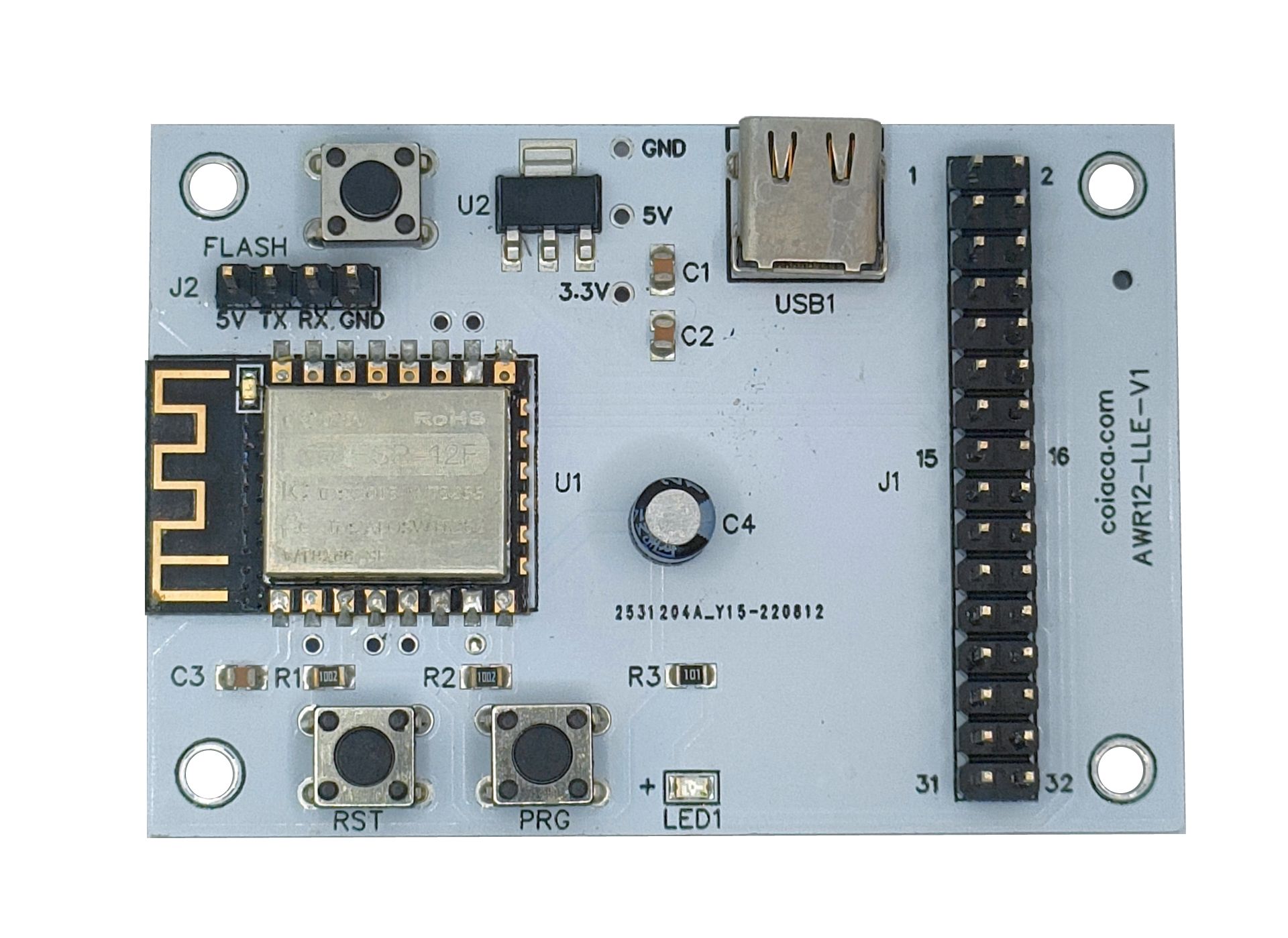
Unlock the power of IoT innovation with AWR12, a cutting-edge circuit board built on the reliable ESP8266-12f. Elevate your projects to new heights with seamless connectivity and smart functionality.
Make It Smart, Make It Simple
Experience hassle-free development with easy wiring and no soldering required, allowing you to focus on bringing your ideas to life.
Tailored to Your Needs
Customize your AWR12 module to suit your specific requirements. Choose between the original ESP8266-12f firmware or opt for various Tasmota ![]() variants pre-flashed for added versatility.
variants pre-flashed for added versatility.
Endless Possibilities
From WiFi thermometers and relays to LED controllers, IR receivers/transmitters, displays, switches, buttons, repeaters, and beyond – AWR12 opens the door to a vast array of applications limited only by your imagination.
Experience the future of IoT development with AWR12 – where innovation meets simplicity.
Main Specs:
- Power Supply: DC12/5V USB type C connector or PINs
- Wireless standard: WiFi 802.11 b/g/n
- Security Mechanism: WEP/WPA-PSK/WPA2-PSK
- Built in indicator led with PIN for connecting external one.
- 1 push button with PIN for connecting external one
- Reset button
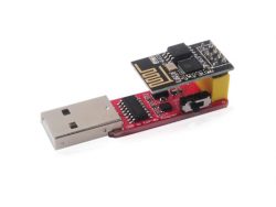
- Program button for easy flashing.
- Digital PINS – Can be used with I2C
- Analog input
PinOut
| J1 | Function | ESP8266-12f PIN |
| 1 | Vcc 5-12v | |
| 2 | Vcc 5-12v | |
| 3 | GND | |
| 4 | GND | |
| 5 | Jmp for external led | |
| 6 | Jmp for external led | |
| 7 | + Ext LED (jmp for internal led) | |
| 8 | GND Ext LED (jmp for internal led) – GPIO0 | GPIO0 (PIN 18) |
| 9 | GND Push Button | |
| 10 | Push Button – GPIO12 | GPIO12 (PIN 6) |
| 11 | Vcc 3.3v | |
| 12 | Vcc 3.3v | |
| 13 | GPIO4 | GPIO4 (PIN 19) |
| 14 | GPIO5 | GPIO5 (PIN 20) |
| 15 | GND | |
| 16 | GND | |
| 17 | Vcc 3.3v | |
| 18 | Vcc 3.3v | |
| 19 | GPIO15 | GPIO15 (PIN 16) |
| 20 | GGPIO2 | GPIO2 (PIN 17) |
| 21 | GND | |
| 22 | GND | |
| 23 | Vcc 3.3v | |
| 24 | Vcc 3.3v | |
| 25 | GPIO13 | GPIO13 (PIN 7) |
| 26 | GPIO14 | GPIO14 (PIN 5) |
| 27 | GND | |
| 28 | GND | |
| 29 | GPIO16 | GPIO16 (PIN 3) |
| 30 | ADC | ADC (PIN 2) |
| 31 | GND | |
| 32 | Vcc 3.3v | |
| J2 | Function | ESP8266-12f PIN |
| 1 (5V) | Vcc 5v | |
| 2 (TX) | TX – GPIO1 | GPIO1 (PIN 22) |
| 3 (RX) | RX – GPIO3 | GPIO3 (PIN 21) |
| 4 (GND) | GND |
Tasmota template: {“NAME”:”AWR12t”,”GPIO”:[320,1,1,1,1,1,0,0,1,1,1,1,1,1],”FLAG”:0,”BASE”:18}


Reviews
There are no reviews yet.